Relevant Installation Video of Rotary Evaporator
Preparations for the Installation
- Check whether the components are complete according to the packing list after opening the package. If there is any missing part, please contact us.
- Remove residues on the glass parts before the assembly and keep the glass contact surface clean; apply vacuum grease to both sides of the seal ring before the installation.
- Tools that might be used in the installation, including allen wrench, screwdriver and other tools, shall be well prepared.
Instructions for the Installation
1. Installation of the Upright Pipe
Rotating in clockwise direction, the upper upright pipe is connected with the lower upright pipe by screw threads (as shown below), on which, the cross clamp, vacuum meter bracket and condenser clamp holder are successively installed.
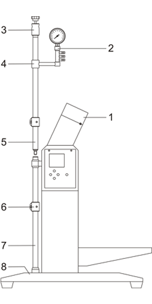
- Nose shell
- Vacuum meter holder
- Condenser clamp holder
- Vacuum meter bracket
- Upper upright pipe
- Cross clamp
- Lower upright pipe
- Base seat
2. Installation of the Rotary Shaft
Set the O-ring on the glass rotary shaft which shall be placed into the nose with the O-ring against the nose shell. (As shown below)
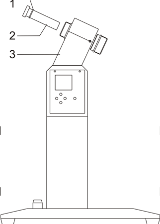
- O-Ring
- Glass rotary shaft
- Nose shell
3. Installation of the Three-Way Flask
Set the retaining nut on the lower bore of glass three-way flask and set the retaining nut check ring on the lower neck of glass three-way flask; then insert the flange seal washer into the three-way flask bore and insert the three-way flask with the seal washer into the upper internal opening of the glass rotary shaft, ensuring the center of three-way flask in the horizontal direction on the left and properly tightening the retaining nut. (As shown below)
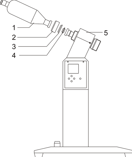
- Three-way flask(replaced Auxiliary condenser)
- Three-way flask retaining nut
- Three-way flask retaining nut check ring
- Flange seal washer
- Nose shell
4. Installation of the Glass Rotary Flask
Set the Teflon seal ring on the assembled glass rotary shaft as shown in the drawing and then set the rotary flask nut on the bottom flask with the check ring on the flask neck. Rotary flask positioning: apply the allen wrench to insert into the hole (inclined left) of nose seat, turning the rotary shaft to make sure the shaft hole coincided with the seat hole, no inserting of allen wrench when the rotary shaft cannot be twisted any more. Last, install the rotary flask with retaining nut and check ring on the glass rotary shaft, tightening the rotary shaft nut. Turn the rotary shaft, ensuring the rotation steady and consistent with the shaft center.
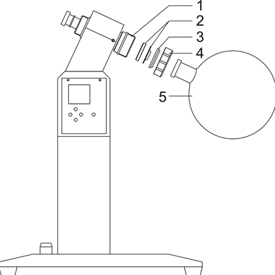
- Coupling
- Teflon seal ring
- Check ring
- Rotary flask nut
- Rotary flask
5. Installation of Auxiliary Condenser and Three-Way Flask
a. Connection of R-1010 / R-1020 / R-1050 condenser with three-way flask
First, secure the pallet on the upright pipe and then place the auxiliary condenser (R-1010 / R-1020 / R-1050 provided with auxiliary condenser) on the mounted pallet, adjusting the height and ensuring the side connecting mouth of auxiliary condenser and three-way flask connecting mouth at the same level, fix the pallet and cross clamp screw .Then set the connecting flange on the bottom connecting mouth of auxiliary condenser with the check ring on the connecting mouth neck of auxiliary condenser. In the same way, set the other connecting flange and check ring on the three-way flask connecting mouth, place the flange seal washer in any of connecting bores of three-way flask or auxiliary condenser and finally tighten the retaining screw and nut. (As shown below)
Note: R1005 is not provided with auxiliary condenser, for which, the below method shall be directly adopted to connect the condenser and three-way flask.
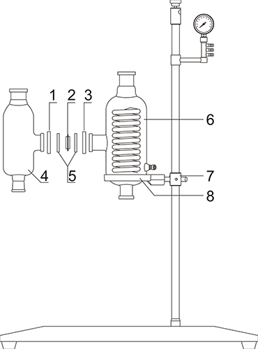
1/3. 60# connecting flange
2. 60# flange seal washer
4. Three-way flask
5. 60# flange check ring
6. Auxiliary condenser
7. Cross clamp
8. Pallet
b. Connection of R-1010 / R-1020 / R-1050 auxiliary condenser with three-way flask:
First set the connecting flange on the bottom connecting mouth of three-way flask and set the check ring on the neck of three-way flask, insert half of the flange seal washer into the three-way flask bore and then set the connecting flange nut and check ring on one end of glass elbow, finally screw the nut and bolt together, adjust the condenser pallet to an appropriate height with the glass elbow in right direction, and in the same way, connect the auxiliary condenser and glass elbow with connecting flange and check ring which shall be tightened at last.
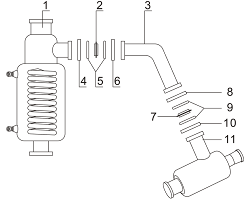
1. Auxiliary condenser (connect to nose shell)
2/7. 60# flange seal washer
3. Glass elbow (deleted)
4/6/8/10. 60# connecting flange
5/9. 60# flange check ring
11. Three-way flask(deleted)
6. Installation of the Receiving Flask
a. R1005 receiving flask installation
Place the receiving flask on the pallet and lift it to a certain height; set the connecting flange on the bottom connecting mouth of receiving flask with the check ring on the neck, insert half of the flange seal washer into the receiving flask bore and then in the same way, set the connecting flange bolt and check ring on the lower connecting mouth of condenser connector; finally insert the lower interface of condenser connector into the other half of the flange seal washer and screw the nut and bolt together. Afterwards, in the same way, successively set the connecting flange and check ring on the lower connecting mouth of condenser and upper connecting mouth of condenser connector, with half of the seal washer inserted into the condenser connector bore. Then raise the height of receiving flask of the fixed condenser connector, ensuring the other half of the flange seal washer inserted in the condenser bore to secure the receiving flask pallet; tighten the connecting flange and make sure that the connecting mouths of condenser, condenser connector and receiving flask are closely meshing with each other without strain so as not to break the glass.
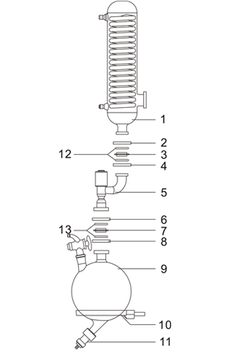
1. Condenser
2/4/6/8.40# connecting flange
3/7. 40# flange seal washer
5. Condenser Connector
9. Receiving flask
10. Receiving flask pallet
11. Emptying valve
12/13. 40# flange check ring
b. Methods for connection of R-1010 / R-1020 / R-1050 auxiliary condenser with receiving flask
Place the receiving flask on the pallet and lift it to a certain height with the cross clamp firmly fixed, then set the connecting flange on the connecting mouth neck of receiving flask and put the automatic switching valve in the flange seal washer. (Note: Automatic switching valve plane toward recycling flask, avoid to be inverted.) The connecting flange and check ring shall also be successively set on the lower connecting mouth of auxiliary condenser. Then regulate the height of receiving flask pallet, ensuring the other half of the switching valve right inserted in the lower connecting mouth bore of auxiliary condenser. Secure the cross clamp and tighten the bolt and nut. (As shown below)
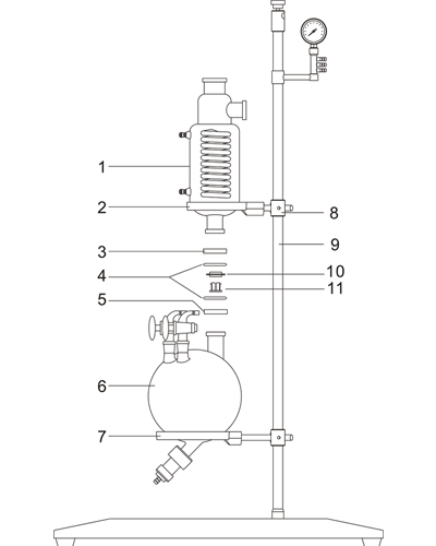
1. Auxiliary condenser
2. Auxiliary condenser pallet
3/5. 50# connecting flange
4. 50# flange check ring
6. Receiving flask
7. Receiving flask pallet
8. Cross clamp
9. Upright pipe
10. 50# flange seal washer
11. Automatic switching valve
7. Installation of the Rest Parts
a. Connection of R-1010 / R-1020 / R-1050 main condenser with auxiliary condenser as well as connection of exhaust nozzle also includes connecting flange, check ring and flange seal washer with the mounting method as described above. (As shown below)
b. Relief valve installation: it shall be directly installed in the receiving flask bore.
c. Vacuum meter installation: secure the vacuum meter on the vacuum meter holder and then together into the vacuum meter bracket and tighten the retaining screw, adjusting the holder to an appropriate height to enable operators to obtain vacuum meter readings by horizontal check.
1. Retaining clamp
2. Main condenser
3/5. 80# connecting flange
4. 80# flange seal washer
6. Auxiliary condenser
7. 80# flange check ring
[title text=”Related Products” tag_name=”h2″ color=”rgb(119, 199, 239)”]
[ux_products ids=”70,849,131,26″]
[title text=”Related Posts” tag_name=”h2″ color=”rgb(119, 199, 239)”]
[blog_posts style=”vertical” columns=”3″ columns__md=”1″ depth=”2″ slider_nav_style=”simple” slider_nav_position=”outside” ids=”6740,6340,4365,4302″ image_height=”89%” image_width=”43″]